
photom – optical communications measuring instrument is,
It has been loved for about 30 years before the dawn of optical communications and has been used on Fields.
Highly Durable and Reliable “photom” brand, Made and Produced in Japan.

Business card size, lightweight
A variety of models that support a wide range of input wavelengths are available.
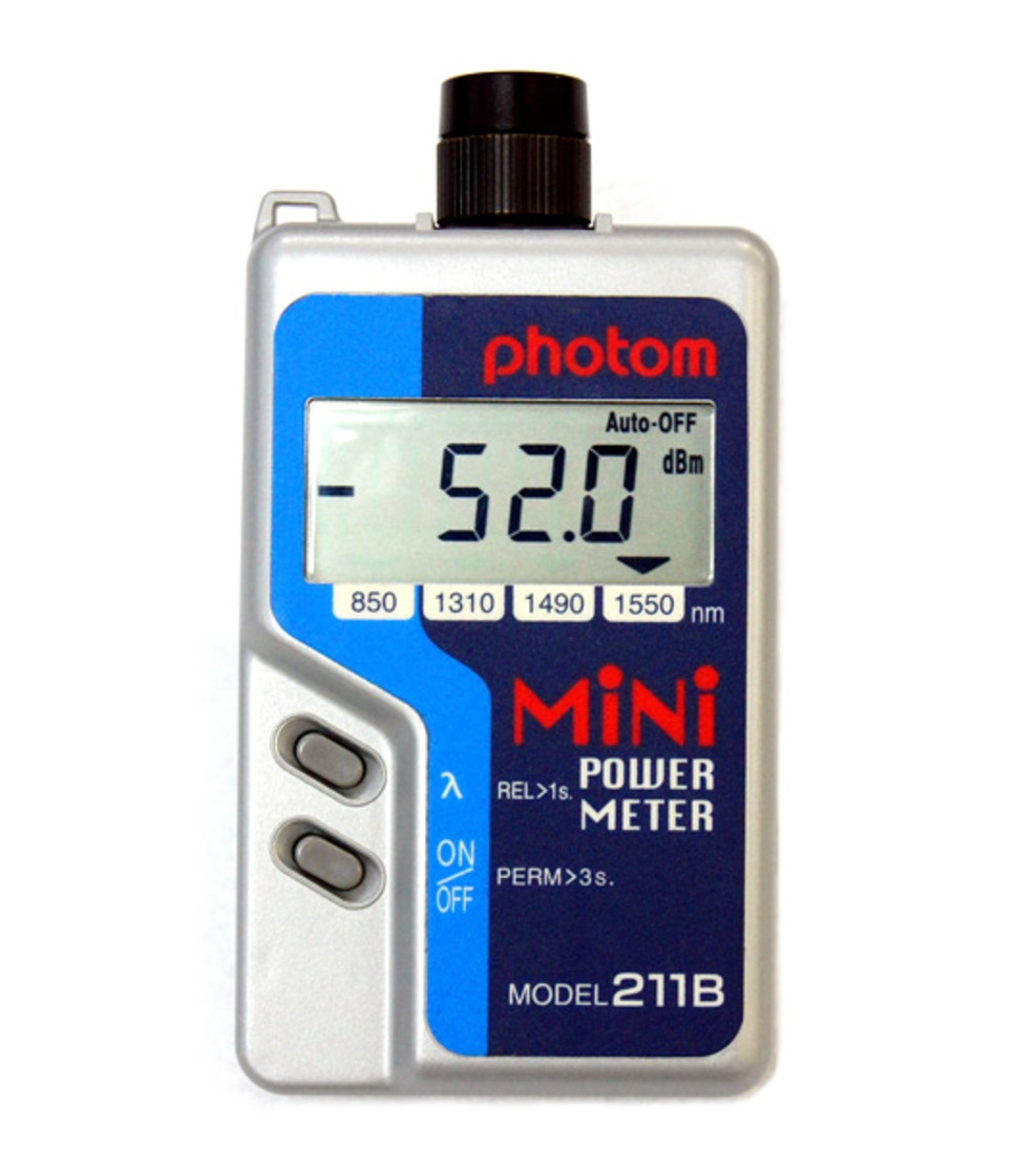
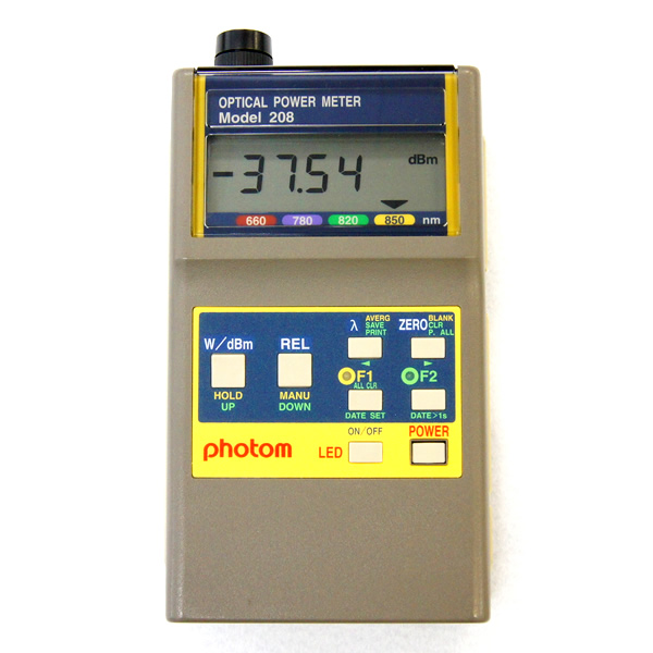
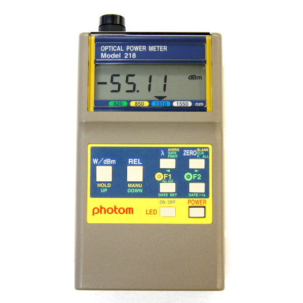
Standard Model
Wavelength:850/1310/1490/1550nm
Compatible fiber: SM 10/125, GI 50(62.5)/125
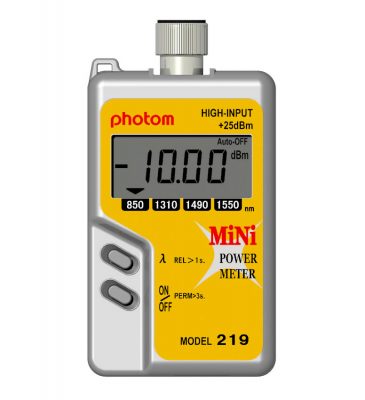
High output Model (up to +25dBm)
Wavelength:850/1310/1490/1550nm
Compatible fiber: SM 10/125, GI 50/125
Buzzer Model (Check light level with a buzzer)
Wavelength 1310/1490/1550nm
Compatible fiber: SM 10/125, GI 50(62.5)/125
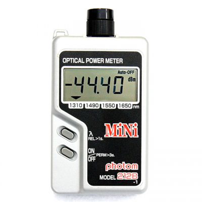
1650nm Wavelength Model
Wavelength:1310/1490/1550/1650nm
Compatible fiber: SM 10/125, GI 50(62.5)/125
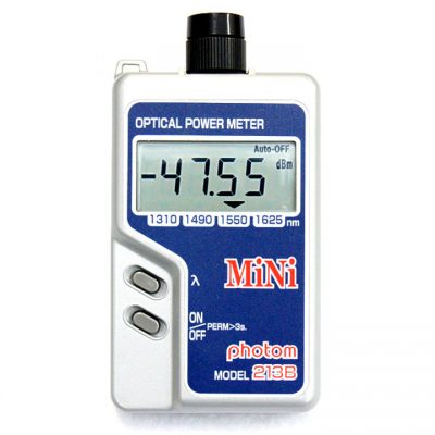
1625nm Wavelength Model
Wavelength:1310/1490/1550/1625nm
Compatible fiber: SM 10/125, GI 50(62.5)/125
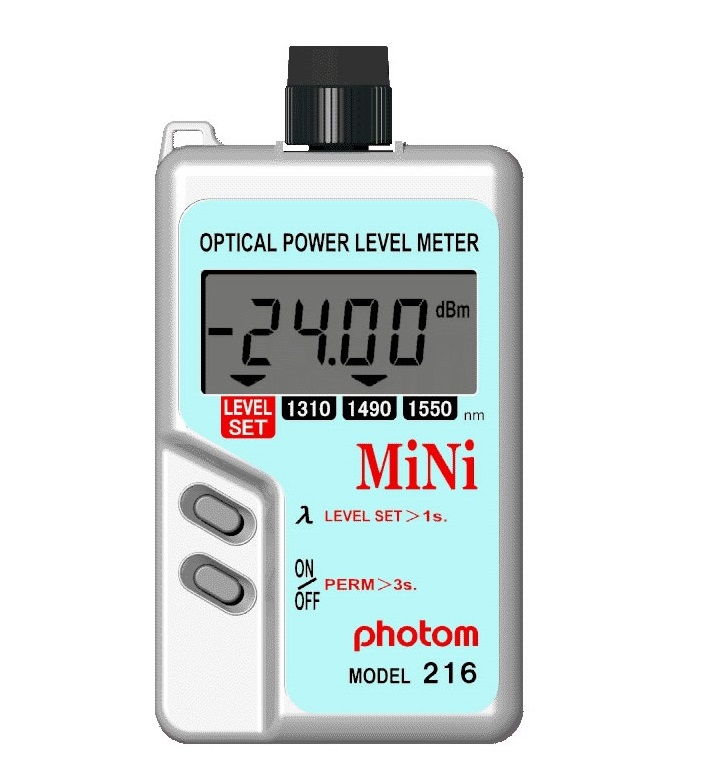
Multifunctional Model
(for POF/H-PCF/GI fiber)
Wavelength 660/780/820/850nm
Compatible fiber: POF、PCF、HPCF、GI
<Click here for usage examples>
Multifunctional Model
(for GI&SM fiber)
Wavelength:850/1300/1310/1550nm
Compatible fiber: GI, SM
Business card size, lightweight
A variety of models are available for a wide range of output wavelengths.
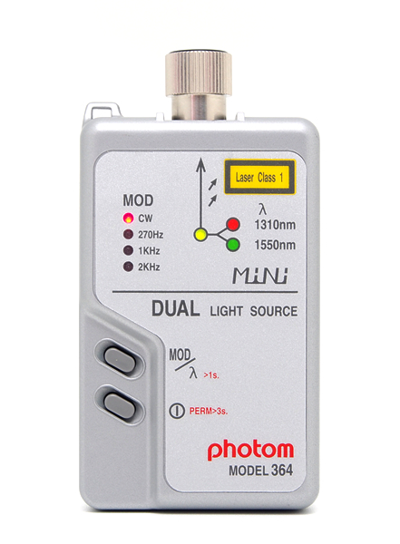
1310/1550nm Dual LD Model
Dual LD switching output with 1 port
Compatible fiber: SM 10/125
*NOT compatible with GI 50(62.5)/125
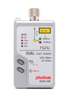
850/1310nm Dual LD Model
Dual LD switching output with 1 port
Compatible fiber: GI 50(62.5)/125
*NOT compatible with SM 10/125
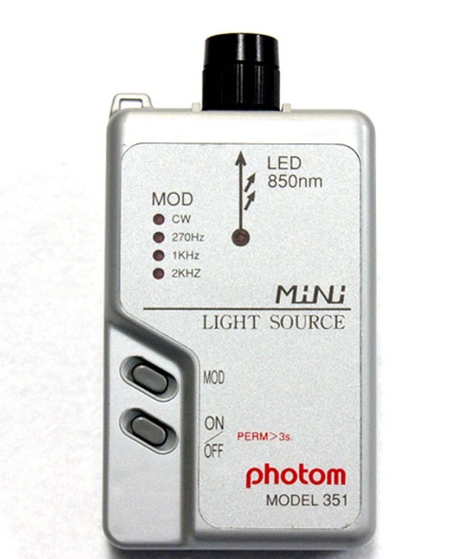
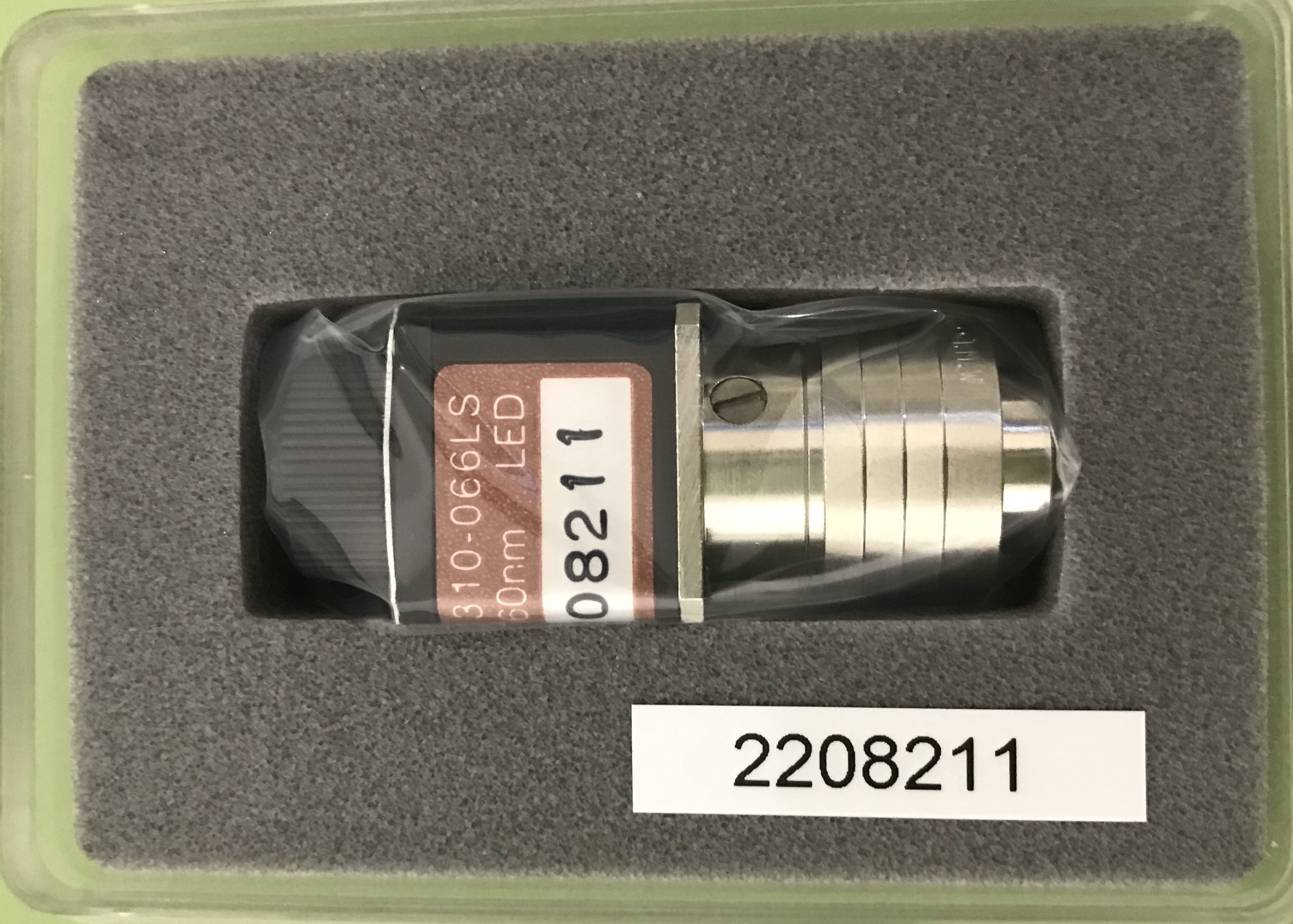
850nm LED Model
850nm output LED light source
Compatible fiber: GI 50(62.5)/125, APF, PCF
*NOT compatible with SM 10/125
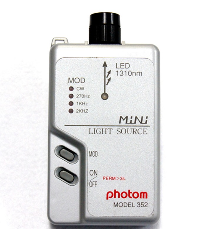
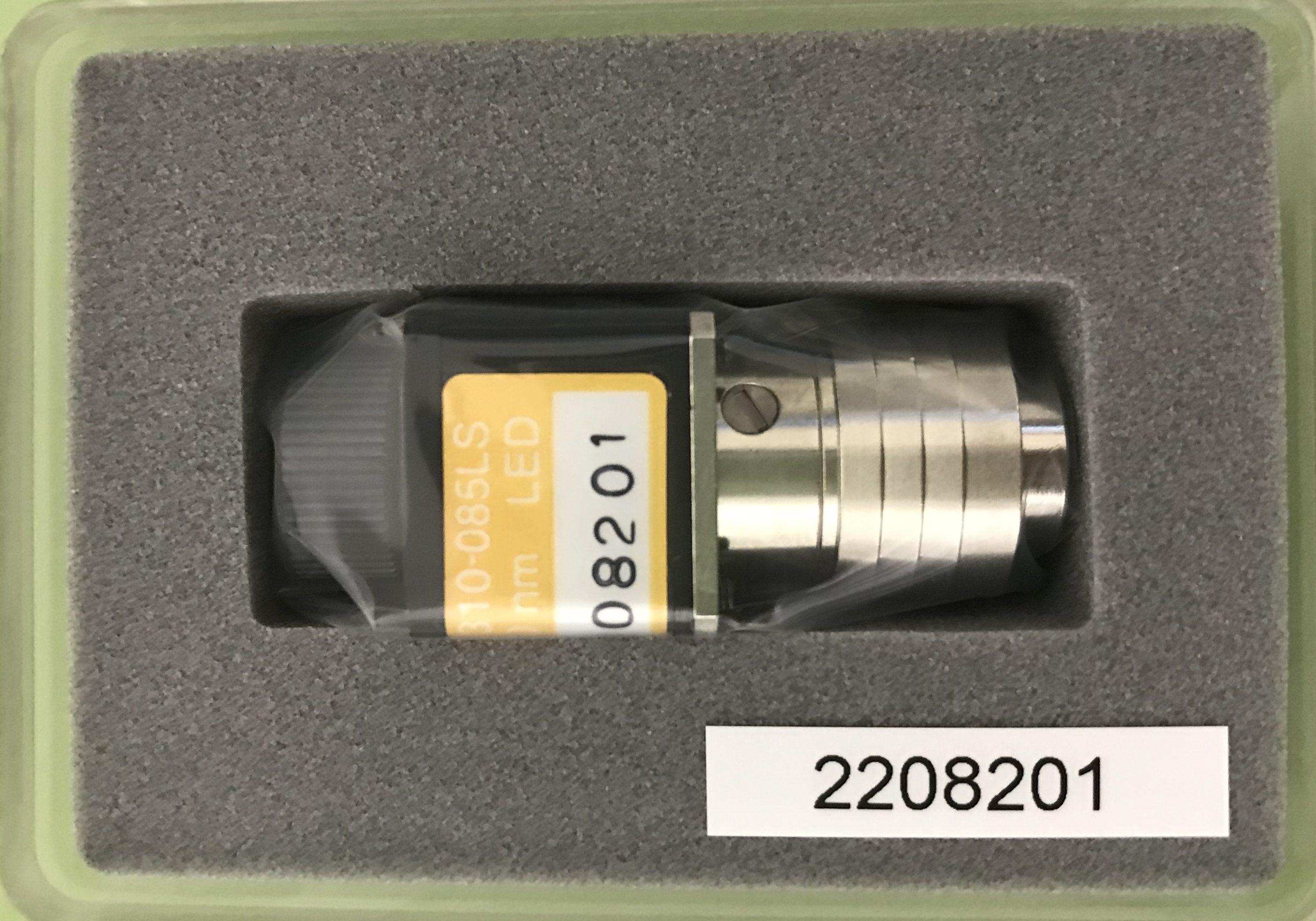
1310nm LED Model
1310nm output LED light source
Compatible fiber: GI 50(62.5)/125
*NOT compatible with SM 10/125, APF, PCF
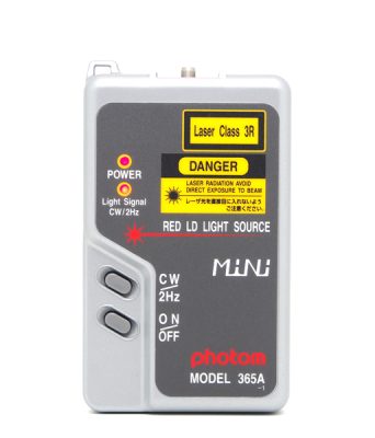
Visible LD Light Model
Reach distance: about 6km
Compatible with any optical connector Φ2.5mm (SM & GI)
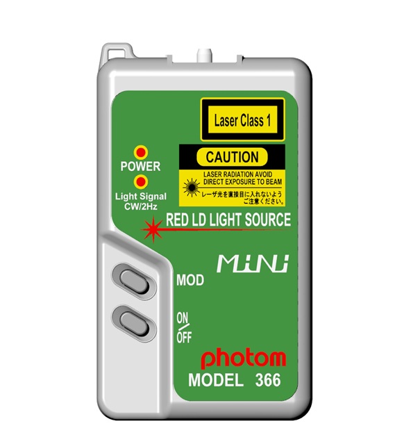
Visible LD (Class 1) Light Model
Laser Safety: Class 1
Reach distance: by around 1km
Compatible with any optical connector Φ2.5mm (SM & GI)
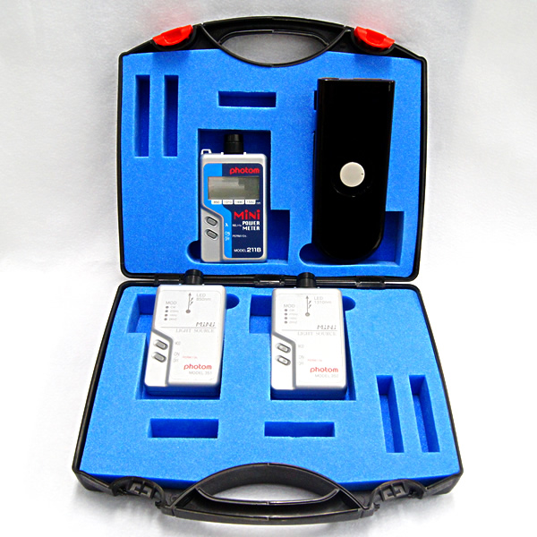
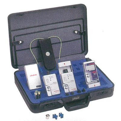
We offer a set that suits your purpose in a lightweight and robust hard case.
In addition to these lineups, we will assort the products upon request.
LAN compatible light source kit
・211B: Wavelength 850/1310/1490/1550nm
・351: LED light source 850nm
・352: LED light source 1310nm
・Mode Scrambler
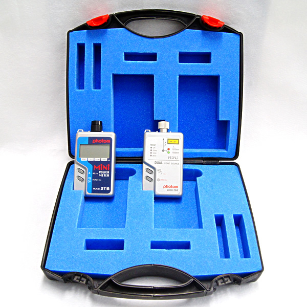
Single Mode(SM) measuring test kit
・211B: Wavelength 850/1310/1490/1550nm
・364: Dual LD light source 1310nm/1550nm
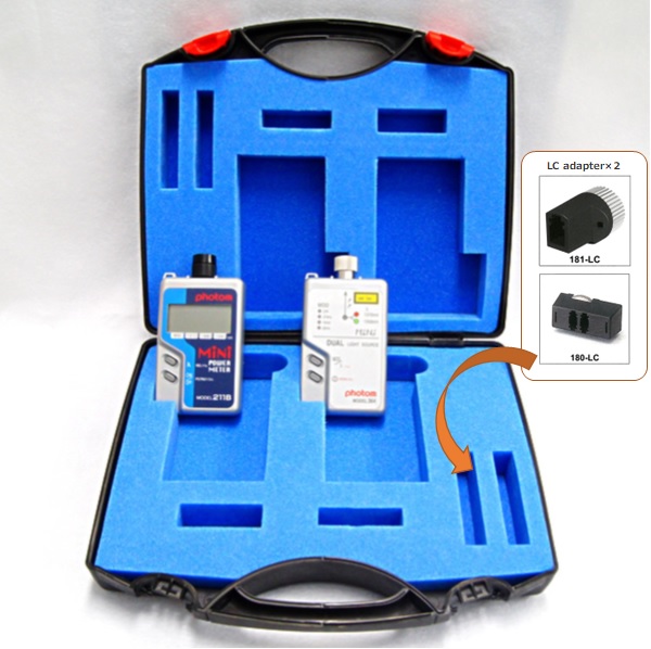
Single Mode(SM) measuring test kit with SC/LC adapters
・211B: Wavelength 850/1310/1490/1550nm
・364: Dual LD light source 1310nm/1550nm
・Available for SC/LC connector

Multi Mode(MM・GI) measuring test kit
・211B: Wavelength 850/1310/1490/1550nm
・368: Dual LD light source 850nm/1310nm
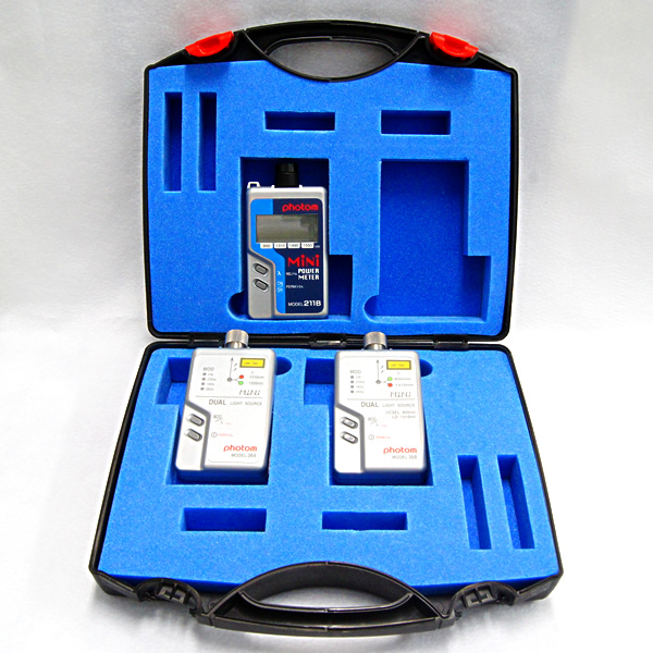
SM/MM・GI measuring test kit
・211B: Wavelength 850/1310/1490/1550nm
・364: Dual LD light source 1310nm/1550nm
・368: Dual LD light source 850nm/1310nm
Multimode fiber test kit
・211B: Wavelength 850/1310/1490/1550nm
・351: LED light source 850nm
・352: LED light source 1310nm
・Mode Scrambler
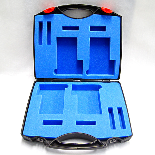
Up to 4 storage images. It can be stored with the body cover and strap attached, and connectors can be stored in the recess.
LED light source unit (for 205A/208)
・Wavelength:660±15nm
・Fiber:POFΦ1、APFΦ1
LED light source unit (for 205A/215/208/218)
・Wavelength:850±30nm
・Fiber:GI50/125、GI62.5/125、HPCF200/230
LED light source unit (for 215/218)
・Wavelength:1310±30nm
・Fiber:GI50/125、GI62.5/125
*NOT compatible with SM 10/125
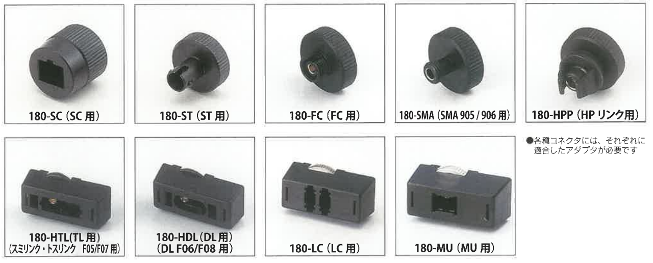
《Attachable products》
MiNi211B/MiNi212B/MiNi213B/MiNi216/205A/215
MiNi351/MiNi352
We accept calibration work for our products and issue a “calibration certificate”.
If adjustment is necessary, we will adjust it.
Also, if a defect (repair required) is confirmed, repair + calibration is also possible.
Optical power meters , light sources , light source units for · 215 205A , in has been accepted calibration.
(We also accept proofreading of products other than the current product. For now, up to about 20 years ago)
Contact Us or until the dealer.
※ Please send only the main unit as much as possible. (To prevent loss of accessories)
This is to prove the normal operation of your measuring instrument.
If the instrument doesn’t display the correct measured value, you can’t use it.
At our company, the accuracy is maintained by conducting a trace with the national standard regularly at the Japan Quality Assurance Organization (JQA), which is an official calibration organization once a year.
We calibrate the regular standard with a JQA calibrated intermediary (temporary standard), and use this regular standard to measure in fields such as development, manufacturing, and inspection.
This standard device is used to prove the normal operation of your equipment. (Proof certificate issued)
It is recommended that calibration be performed once a year.
The period of storage is usually about 1 week to 10 days.
Inquiry of calibration, etc. phone · FAX · E-mail I have heard.
Please fill out the form below and apply.
We accept repairs of broken products.
In order to respond quickly to repaired products,
please let us know as much as possible about the occurrence status, frequency, phenomenon, and contact information of the user.
Please fill out the form below and apply.
※ Please send only the main unit as much as possible. (To prevent loss of accessories)
1 If there is a failure due to manufacturing reasons within the warranty period (within 1 year after delivery to the customer), we will repair it free of charge.
It is paid in the case corresponding to the item in the following even within the 2 warranty period
failure due to force majeure, such as the use methods and natural disasters wrong –
failure due to severe use more than the environment that is defined in the operation manual
, our company or our Failure caused by modification or repair by someone other than
3 Inspection and calibration within the warranty period will be charged.
4 Repair or calibration may be refused in the following cases:
・ If it is more than 7 years after manufacturing and parts are difficult to obtain
・ Products that have been over 5 years after discontinuation of production
・ Reliability after repair due to significant wear and deterioration
・If it is determined that the product cannot be maintained
・ Remodeling or repairs by other than our company
・ Parts or equipment cannot be secured
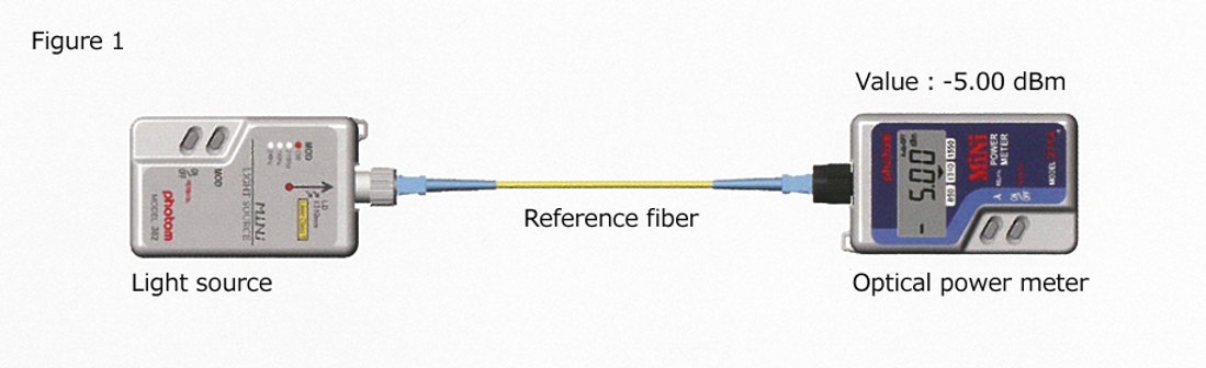
1. Connect the reference fiber from the light source to the optical power meter as shown in Fig. 1,
and display the output from the light source on the optical power meter.
Let this displayed value be P1.
(P1: Displayed value of optical power meter when only reference fiber is connected)
Figure 1 , Example : P1 = -5dBm
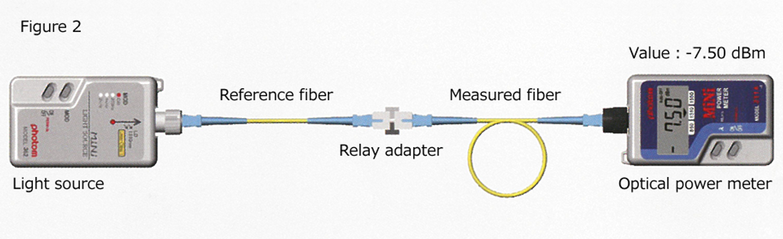
2. Disconnect the reference fiber and the optical power meter from the connection in Fig. 1,
and connect the fiber to be measured via the relay adapter to the disconnected section as shown in Fig. 2.
At this time, the output of the light source via the reference fiber and the measured fiber is displayed on the optical power meter.
Let this displayed value be P2.
(P2: Optical power meter display value when the reference fiber and the measured fiber are connected)
Figure 2 Example: P2 = -7.5dBm
3. The difference between the optical power meter readings of P1 and P2 is the attenuation (loss) of the measured fiber.
Calculation formula: P2-P1 = loss of the measured fiber
[ Example: -7.5dBm – ( -5dBm ) = -2.5dB ]
(1) From the light source output when the reference fiber is connected, how much output has dropped by connecting the fiber to be measured. The amount of this drop is the attenuation of the fiber to be measured.
(2) Our power meter has a “relative value measurement function”. (Excluding 216 for current products)
This series of “P2-P1 = loss of fiber under test” can be simplified.
After measuring the reference fiber, press the REL (dB) switch to set the reference value, and then connect the measured fiber, the attenuation of the measured fiber can be displayed automatically.
The actual procedure:
Connect as shown in Fig.1 and measure → press REL (dB) → remove power meter.
Connect the measured fiber to the removed section via a relay adapter as shown in Fig. 2.
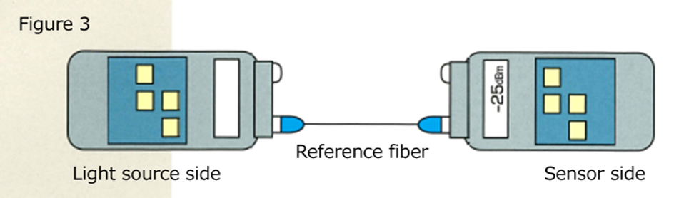
1. Connect the reference fiber from the light source to the optical power meter as shown in Fig. 3,
and display the output from the light source on the optical power meter. Let this displayed value be P1.
(P1: Displayed value of optical power meter when only reference fiber is connected)
Figure 3 Example: P1 = -25dBm
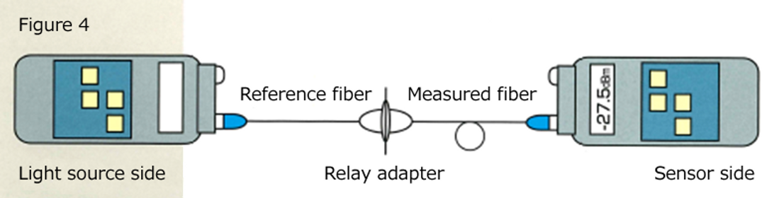
2. Disconnect the reference fiber and the power meter on the sensor side from the connection in Fig. 3, and connect the fiber to be
measured via the relay adapter to the disconnected section as shown in Fig. 4. At this time, the output of the light source
via the reference fiber and the measured fiber is displayed on the power meter on the sensor side. Let this displayed value be P2.
(P2: Optical power meter display value when the reference fiber and the measured fiber are connected)
Figure 4 Example: P2 = -27.5dBm
3. The difference between the optical power meter readings of P1 and P2 is the attenuation (loss) of the measured fiber.
Calculation formula: P2-P1 = loss of the measured fiber
[ Example: -27.5dBm – ( -25dBm ) = -2.5dB ]
(1) From the light source output when the reference fiber is connected, how much output has dropped by connecting the fiber to be measured. The amount of this drop is the attenuation of the fiber to be measured.
(2) Our power meter has a “relative value measurement function”.
This series of “P2-P1 = loss of fiber under test” can be simplified.
After measuring the reference fiber, press the REL (dB) switch to set the reference value, and then connect the measured fiber, the attenuation of the measured fiber can be displayed automatically.
The actual procedure:
Connect as shown in Fig. 3 and measure → press REL (dB) → remove the power meter on the sensor side.
Connect the measured fiber to the removed section via the relay adapter as shown in Fig. 4.
This displays the attenuation of the measured fiber.
〒110-0005 東京都台東区上野1-9-2 ビルボビル 2F
TEL:03-5807-6081